Minimum Brace Strength and Stiffness
1.
Columns:
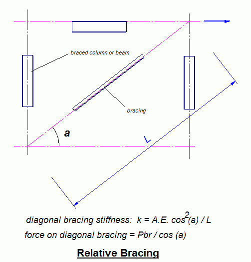
Relative Bracing:
Pbr = 0.004 Pr
ßbr = 2 Pr / (0.75 Lb)
LRFD
ßbr = 2 (2 Pr / Lb) ASD
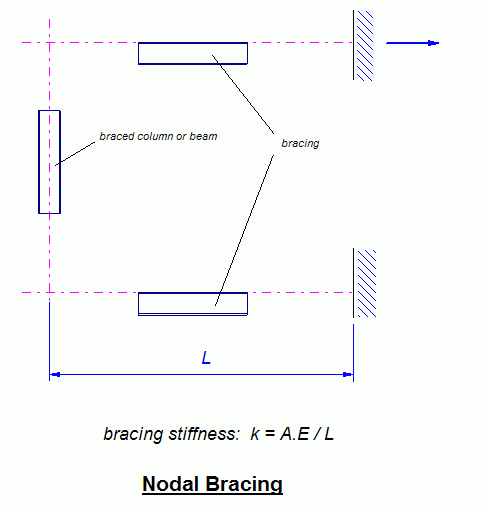
Nodal Bracing:
Pbr = 0.01 Pr
ßbr = 8 Pr / (0.75 Lb)
LRFD
ßbr = 2 (8 Pr / Lb) ASD
Pr = required axial compressive load
Lb = distance between braces
2. Beam Lateral Bracing:
Relative Bracing:
Pbr = 0.008 Mr.Cd / h0
ßbr = 4 Mr.Cd / (0.75 Lb.h0)
LRFD
ßbr = 2 (4 Mr.Cd / Lb.h0)
ASD
Nodal Bracing:
Pbr = 0.02 Mr.Cd / h0
ßbr = 10 Mr.Cd / (0.75 Lb.h0)
LRFD
ßbr = 2 (10 Mr.Cd / Lb.h0)
ASD
Mr = required flexural moment
Lb = distance between braces
h0 = distance between flange centroids
Cd = 1.0 for bending in single curvature; 2.0 for
double curvature
Notes:
The brace stiffness affects the brace force, the larger the brace
stiffness, the smaller the brace force
In above equations, bracing is assumed to be perpendicular to the
member to be braced.; for inclined or diagonal bracing, the brace strength
(force or moment) and stiffness (force per unit displacement or moment per unit
rotation) must be adjusted for the angle of inclination
Relative brace controls the movement of the brace point with
respect to adjacent braced point
Nodal brace controls the movement at the braced point without
direct interaction with adjacent braced points
Pbr shall be combined with the lateral forces from
other resources such as wind or seismic loading
When Lb is less than Lq, where Lq
is the maximum unbraced length for the required column force with K=1, then Lb
is permitted to be taken equal to Lq
Beam lateral bracing shall be attached near the compression
flange, except for a cantilevered member, where an end brace shall be attached
near top (tension) flange. Lateral bracing shall be attached to both flanges at
the brace point near the inflection point for beams subjected to double
curvature bending along the length to be braced.

 Reference: AISC 16
th Edition